It has been quite a while since I wrote anything technical. Or in general about the stuff I actually do. Well, this post is about stuff I'm currently working on: a blob detection program for an old touch table of my university. We also have a MS Surface table here but I don't really do windows programming for fun any more. Maybe I should try booting the MS Surface table from a Linux live USB stick…
A, well, the old touch table was assembled a few years ago from students I unfortunately never met (before my time). In there are infrared LEDs that flood the table with infrared light as well as a camera that permanently films the surface of the table (from below that is). When a finger touches the table the surface and the finger reflect additional infrared light. This light is then captured by the camera. The purpose of the program I'm currently working on is to detect the infrared light blobs that belong to fingers.
Touch table from below without and with a hand on it
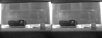
The small figure shows what the touch table looks like for the camera. The left side shows the "background". Basically this picture is what the camera always sees. No mater what is above the table each pixel is at least as bright as in this "background". It's actually the mean image of 60 consecutive images. This way the noise of the camera is filtered out. The right side shows a normal input image with 5 fingers touching the surface and a lot of noise in it.
Just in case someone notices: These images were taken when the table was partially disassembled. I played around with different cameras (another story) and this was a more or less comfortable way to do it. That's the reason why the beamer is almost in the center of the image and only a part of the actual surface is visible. But this was enough to test and develop by so I used a few hundred captured frames as sample material.
The ultimate goal is to throw the right picture into the detector program and getting the coordinates of the 5 fingers in return. Well, for a human this is an easy task. Unfortunately I can't afford to hire someone always watching the table from below and entering the coordinates into a computer with about 17ms delay. So I have to teach computers to do it for me. Turns out our brain does a lot of magic when we see the 5 fingers and it's a lot harder to teach a computer to do something similar. It took me the better part of the last 1½ weeks.
I already tried the same thing on the same table about 1½ years ago. Back then with more "established" approaches. That is filtering the image with a Gaussian blur or doing some temporal filtering (e.g. only count fingers that are there for 5 consecutive frames). These techniques do work but bring in their own set of problems. I never got the Gaussian blur fast enough on one core to filter 30 frames per second on a 640×480 video. And the temporal filtering makes fast movements and short touches almost impossible to detect.
But back then I primarily failed because of two problems:
- The touch table is not uniformly lit and not uniformly sensitive. When someone touches the table the camera see different brightness values depending on where you touch it. This makes it very hard to use a simple brightness threshold to detect a finger. For example in one area pixels only get brighter than 140 if someone touches the table. In other areas this value can be quite a bit off (e.g. 100 or 190).
- The arm itself is actually quite as bright as the fingers. Looking for the center of bright areas will also detect the arm as a finger, albeit a gigantic one. In the worst case it almost absorbs the fingers.
Since this first failed attempt I had some ideas to tackle at least the first problem. I thought I could avoid the second problem I wasn't that lucky. So I had to solve it. I tried quite a few different ideas. For example filtering for specific brightness increases followed by matching brightness decreases (I think one can call that the second spatial derivative). And about 2 hours ago I finally succeeded in that endevour. So here is how it works right now…
Normalization
I need to determine some characteristics of the table before actually detecting stuff. You need to know your enemy, right? On my first attempt this only involved two steps:
- Capture a background image
- Figure out what pixel on the camera image corresponds to what position of the table surface (haven't done that yet)
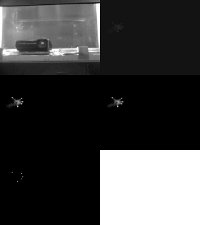
The background, the touch map and the differnce between them

To get hold of the differences in sensitivity on the table I added a third characteristic: A map of how strong the brightness changes when someone touches the table. I simply called it the "touch map" (well, naming things is difficult). Basically it's recording the maximal brightness of each pixel while you touch the table every where. With that data we know the brightness value when no one touches the table (the background) and when someone touches it (the touch map). And these values can be different for each pixel.
With these two per pixel values we can "normalize" the brightness of any pixel into a uniform one. If a pixel is a bright as the background the value will be 0 and if it is as bright as the touch map it will be 1 (or 255 for 8 bit integers). Any further code can work on this "normalized" brightness and is independent on the actual sensitivity of the table.
And the sensitivity can vary quite a bit. The second figure shows the background and the touch map as well as the difference between them. I only touched half the visible surface and you can see that area nicely on the rightmost image. Some variations in the sensitivity come from my lazy "touching the table every where". I did this a bit to often so it's not the best touch map but it works.
As extra fine tuning the touch map is blurred slightly. Each pixel is taken as the mean value of a 3×3 pixel square with the pixel in the center. This is fast and gives a nice 1 pixel "safety margin" around especially sharp edges in the touch map. E.g. areas surrounding the white "blind spot" of the table reduce the sensitivity around them. This prevents the normalization from amplifying noise around these areas into insanely bright spots.
I also added a "touch range threshold". A pixel needs a meaningful difference between its background and touch map value. If this difference is below e.g. 10 we don't do any further stuff with this pixel. This prevents the normalization from amplifying noise in regions that were never touched.
Background with noise
After many noise filtering experiments (simple blurring, eliminating specific 1 and 2 pixel patterns, etc.) I settled for a somewhat contra intuitive approach. Usually the background is captured by calculating the mean brightness of several consecutive frames for each pixel. In this mean brightness the camera noise eliminates itself (it's evenly distributed in time). This gives a nice and noise free background.
However when you subtract this mean background from an input frame you get the difference from the background… and a lot of noise. I found myself spending more and more time on filtering that noise. Out of curiosity I started to capture minimal and maximal noise values for the background as well. For each pixel that is the smallest (min) and largest (max) brightness observed while capturing the background. As it turns out this noise is not evenly distributed over the entire table (spatial). And anyway I'm only interested in pixels that are above the noise level of the camera. Otherwise it's very difficult to differ between noise and a valid increase in brightness.
End of story: Right now I'm just capturing the maximal observed brightness when creating the background. This way the background also contains the maximum noise level. Now when we subtract the background from an incoming frame we get a simple noise filter for free. It's not great but actually does the job without resorting to temporal filtering and is as fast as it can get.
The actual blob detection
Stages of the detection pipeline
Whenever the camera sends a new frame it runs though the following pipeline:
- Original input frame: The stuff from the camera.
- Subtract background: Remove the brightness we know is always there as well as the noise. Note that the brightness in this frame of the figure is pushed by 32 to make the actual changes more visible.
- Normalize difference: Use the touch map to map the difference to a brightness uniform across the entire table.
- Simple blur: Do a simple 3×3 mean blur on the uniform brightness values. This step actually served a different purpose for another idea (smoothing the brightness gradients so slope, high point and low point detection would work better). However it also serves well to suppress some hardcore 1 and 2 pixel noise as well as occasional 1 pixel spikes from the normalization (pretty rare thanks to the same blur on the touch map itself).
- "Spider" amplification… sorry for the lack of a better name. This step detects pixels that belong to fingers and suppresses pixels that belong to other stuff (e.g. arms).
The figure shows the frame after each of these steps. The order of the images in the figure is left to right and top to bottom.
The "spider" amplification is the part I just finished several hours ago. For each pixel the program looks into 4 different directions. Like the legs of a spider, hence the name. Ok, a spider has 8 legs but this is what I thought of when first visualizing the algorithm. We go e.g. 8 pixels in each direction and compare the brightness value there with the brightness of our own pixel. If the brightness difference between the outer and center pixel is above a threshold (e.g. 75) the "leg" is counted. If it's below the "leg" is ignored.
The new brightness value of the center pixel is then calculated as the mean value of all counted "legs". This alone gets rid of almost the entire arm and leaves the fingers very bright. However it also generates some "ghost" artifacts. Like 4 different versions of the image just a bit darker and offset into each of the 4 directions. This however can be suppressed by only counting center pixels with at least 3 "legs" since the ghosts are created by center pixels with only one intact "leg".
The distance or "leg" length has to be configured to match the maximum blob size. Right now I got the best results with a value of 8 but this is very dependent on the size of the table and resolution of the camera. The last image (lower left) in the pipeline figure shows the results of the spider amplification with a distance value of 8.
Further stuff
All parts of the detector program are quite simple right now (code wise). Therefore I have good hopes to achieve 60 fps on a 640×480 video in realtime. The algorithms themselves at least look quite well suited for SIMD or GPU parallelization. However I would prefer to have it run on a single CPU core. Less data transfer and keeps the GPU and most parts of the CPU free for the game. Yes, the entire thing is only to make the touch table usable for a specific game I have in mind. Let's hope it works out. :)
Now the sun has risen again. It's time to go to bed.